Coating Thickness Measurement (Manuel)
Discover the PAINT BORER TCG coating thickness gauge, specially designed for the precise measurement of “thick layers” up to 6000 µm. With the choice between analogue evaluation via magnifying glass (PAINT BORER TCG “analogue”) or digital evaluation via software (PAINT BORER TCG “digital”), this device offers a reliable solution for measuring coating thicknesses on non-metallic substrates such as concrete, plaster, screed, wood and plastic.
Purpose and application: The measurement of thick layers over 2000 μm on non-metallic substrates (concrete, plaster, screed, wood, plastic etc. …) is a potential technical, possibly also financial challenge for the user. Reliable non-destructive methods on non-metallic substrates, often cause a distinct price and require uncomfortable calibration. The destructive measurement by means of a simplified wedge cut method by means of punctual (and, if necessary, easily repaired) damage to the “thick” layer, offers, in addition to the uncomplicated application, a significantly more favourable and welcome alternative for many users.
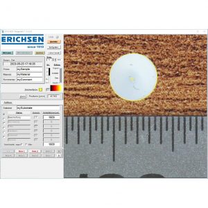
Principle of the test: The measuring principle of the PAINT BORER TCG follows the standardised wedge cutting method, in which the sample is drilled at a defined angle. Compared to the established Paint Borer 518 MC/USB, which is suitable for layer thicknesses up to 2000 µm, the PAINT BORER TCG offers a three times higher measuring range of up to 6000 µm, which is explicitly suitable for “thick layers”.
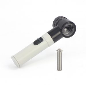
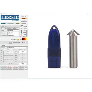
Two options are available for evaluation. The first option is an illuminated magnifier with scale in 0.1 mm resolution (75 μm per scaled graduation mark). (PAINT BORER TCG “analogue”) The second option is the software “WedgeSoft X”, for importing and processing separately taken images (from digital microscope, smartphone or tablet). (PAINT BORER TCG “digital”)
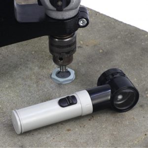
The operation of the PAINT BORER TCG is simple. The special drill has a shank diameter of 10 mm (suitable for most common drilling machines). Drill at an appropriately low speed (if necessary, optimise individually according to the result achieved) as vertically as possible through the layer to be measured until the substrate is visibly (possibly noticeably) reached during drilling; especially with mineral substrates, do NOT drill clearly into the substrate. If necessary, the vertical guidance of the drilling unit can also be optimised by using a lever-operated lifting and lowering drill stand (to be provided by the user).